I’m writing this in a bus so ignore some mistakes that might be there lol. I couldn’t wait to write this post so here it is.
If you read my previous post, you must know the first actual 3D design I’m creating, and it failed. Horribly. The actual pictures of the fail and the design are available in my previous post. However, after discussing it with my professor and a TA, I realised that my mistake was my slicing of the design when I uploaded it to the PRUSA slicer.
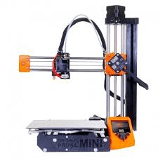
Let me back up for a minute. This is the 3D printer I used (credits: google photos):
Now, when you design something in a CAD (computer aided design) software like Fusion 360, which I used, you generally export it as an STL file. From google, “STL stands for stereolithography, standard triangle language, or standard tessellation language.” In simple jargon, because the computer can’t read your actually design, just like a computer can’t read python properly, it needs a compiler-like program to break it up into things the printer can actually understand. In this case, triangles. Once sliced, this is exported as a gcode file (file name not important) onto a USB drive from a computer, which is then plugged into the actual 3D printer.
My mistake occurred when actually creating the slice for the design. My design was fine, but I didn’t place the lid on the ground, and so when the computer ran its slicing code, my lid was literally in the air. For obvious reasons, the 3D printer can’t print in the air.
So when the 3D printer started printing the layer of the design where the lid started, it got all messed up because the PLA wasn’t on the ground, hence the royal screw-up. In hindsight, it’s a pretty stupid mistake, lol. First time for everything.
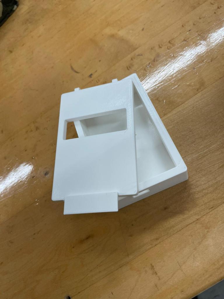
After fixing the mistake, the above is the finished print!! FIRST 3D PRINT!! Although, there’s a reason this post is named the “Sequel” vs “Finale”.
Celebrations aside, this print has a few problems. One, the box itself doesn’t accommodate the breadboard. It’s simply too small. Just a few minor changes to the design on Fusion 360 will make the inside dimensions bigger and problem solved.
Same for the holes at the back of the lid. The wire doesn’t seem to fit in the hole, so I probably will increase the radius by 0.5 to 1 mm. Undecided.
Other than that, I like the thickness of the actual box, and the fillets have come out nicely. Fillets are the rounded corners all around the print. I can change how much they curve, and with what shape. The final result seems perfect. I also like the idea of making the rectangular hole on the lid side-to-side. Basically, as seen in the previous post, there is a screen which needs to be seen and thus a hole needs to be made. Some other people were creating precise rectangular holes exactly where the screen would be. I figured if the screen should change position a few mm to the left or right, the entire design would need to be reprinted; easier is to just create it from edge-to-edge.
I’m not sure whether I’ll edit this post or create a new one for the final print, but whatever it is I hope happens soon. I’ll be back.
